
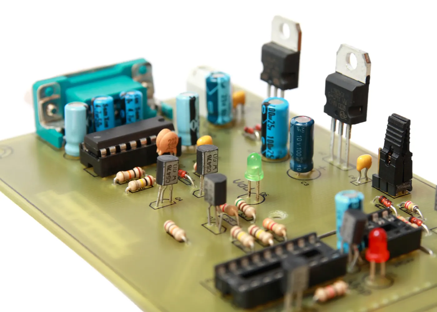
A design for manufacturability review helps identify layout, component, and material choices that may make a PCBA harder to assemble, solder, inspect, or reproduce. In through-hole assembly services, DFM is especially useful because many assembly problems stem from decisions made before the board enters production. Hole and pad design, component spacing, solder access, thermal mass, and inspection access can all affect build quality. Reviewing those issues early helps keep projects on track and prevents surprises once assembly gets underway.
What A DFM Review Checks Before Assembly
A DFM review checks whether the board design, component choices, and documentation give the assembly provider enough information to build the PCBA consistently. For through-hole assembly services, that review is usually tied to the assembler’s equipment, soldering process, inspection method, and experience with similar board types. DFM is a review of whether the design can move through assembly without avoidable clarification, rework, or process changes.
The assembler reviews issues that could affect component insertion, soldering, thermal behavior, inspection, documentation, or repeatability. If the review identifies a concern, the next step is usually a design clarification, file update, or engineering discussion before fabrication or production begins.
Hole and Pad Design
Hole and pad design affects how well through-hole leads fit into the board and how reliably solder forms around the joint. If the hole is too tight for the lead, component insertion can become difficult or inconsistent. If the hole is too large, the joint may be weakened by solder voids, a component that shifts during soldering, or poor electrical contact. Pad design also affects solder joint strength and the available area for soldering.
DFM helps confirm that the hole and pad design fits the component, the build process, and any applicable standards. A buyer or engineer may see the board as complete because the circuit is correct, but the assembler may see features that are harder to build repeatably. Catching those issues before production helps reduce insertion problems, solder defects, and board-level rework.
Component Placement and Assembly Access
Component placement affects whether parts can be inserted, handled, and soldered without creating unnecessary assembly problems. A layout can be electrically correct and still create build issues if components are crowded, tall parts limit access, or bulky connectors interfere with soldering. While these do not always indicate a flawed design, they can create assembly constraints that should be reviewed against the assembler’s equipment and workflow.
Through-hole assembly may involve hand insertion, selective soldering, wave soldering, or manual soldering in specific areas. Each method has access requirements. DFM helps determine whether the layout provides the assembler with enough room to place components, support the board, apply solder, and avoid disturbing nearby parts during the build.
Thermal Behavior During Soldering
Thermal behavior must be considered because some board features pull heat away from the solder joint. Large copper areas, ground planes, high-mass connectors, shields, and heavy components can make soldering less consistent if the design does not account for heat transfer. Conversely, excessive heat, extended dwell time, or uneven heating can pose other risks.
A DFM review helps flag areas where thermal mass may affect solder flow or require process adjustments. The assembler may need to review the layout, component type, board thickness, copper weight, and soldering method before confirming how the board should be built. This review can help identify soldering risks before they create inconsistent joints or rework during production.
Inspection Access and Verification
Inspection access is different from assembly access. Inspection access is important so the finished joint, component orientation, polarity mark, or component marking can be checked after assembly. If important features are blocked, the assembly provider may have less ability to verify the work or document the result.
DFM can identify areas where inspection will be difficult before the board is assembled. Inspection concerns may include hidden solder joints, obscured markings, unclear polarity indicators, or missing orientation details. The review gives the assembler a chance to request clarification before defects or uncertainty appear during production.
Documentation Needed for a Useful DFM Review
A useful DFM review depends on complete and accurate documentation. The assembler needs more than a general board description. At a minimum, the review may require fabrication data, assembly drawings, the bill of materials, component placement data, approved alternates (when applicable), and notes on special soldering, handling, or inspection requirements.
Missing or unclear documentation slows the review and increases the chance of follow-up questions during production. If a component has an unusual fit, heat sensitivity, orientation concern, or substitution limit, the assembler needs that information before the build begins. Good documentation helps the assembly provider review the actual production requirements rather than making assumptions based on incomplete files.
DFM Reduces Rework and Delays
DFM reduces rework and delays by moving assembly questions earlier in the process. Problems found during review are usually easier to address than problems found after boards are fabricated, components are purchased, or production is scheduled. A hole sizing concern, blocked soldering area, unclear orientation note, or thermal issue may be manageable early. During production, the same issue can trigger rework, engineering review, schedule changes, or customer approval delays.
Complex boards may still require careful assembly planning, process review, and customer communication before production. DFM helps the assembler and the customer identify known build risks before they become production problems. For through-hole assembly services, that early review can improve communication, reduce avoidable defects, and help the build move through assembly with fewer surprises.
Work With Siemens Manufacturing for Through-Hole Assembly Services
Siemens Manufacturing supports through-hole assembly with DFM and BOM review before production begins. That review helps identify concerns tied to component fit, soldering method, inspection access, documentation, and production requirements before the board reaches the line. Our through-hole capabilities include wave soldering, selective soldering, robotic soldering, axial insertion, and DIP insertion, giving the team several process options for different board designs and production requirements.
If you have a through-hole or mixed-technology PCBA project, contact Siemens Manufacturing to discuss your design files, assembly requirements, testing needs, and production timeline. Our team can review the build requirements and help determine the right assembly approach for your board.